Electronics design
The last fabrication technique we learned in this course involved designing PCBs. The heart of the PCB we designed was an ATtiny1614 microcontroller. The board was intended to have functionality ideally related to our final project.
Since I required a different chip for my final project, I chose a relatively simple design that included an I2C connection, a UPDI header, a serial header, and two LEDs (one to indicate power and another controlled by a button). I also incorporated a few capacitors to smooth out the electrical supply. You can find the KiCad files here.
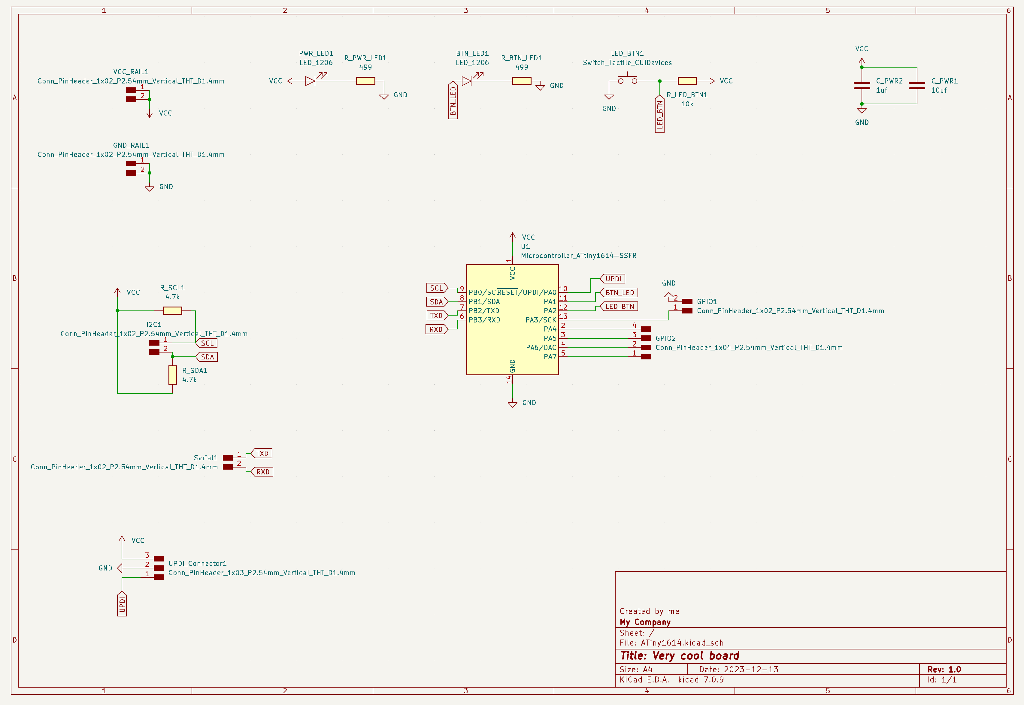
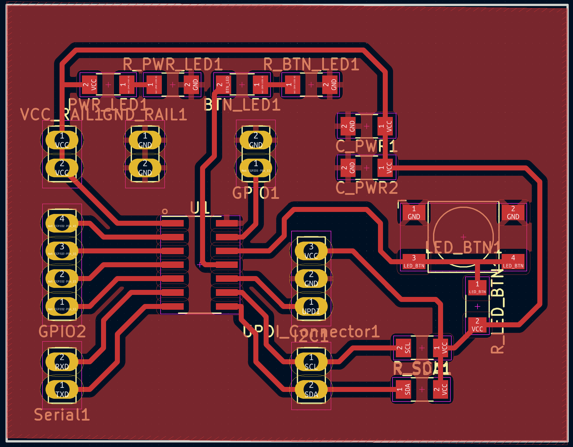
After finalizing the schematic, the next step was to lay out all the components on the PCB and establish the necessary connections.
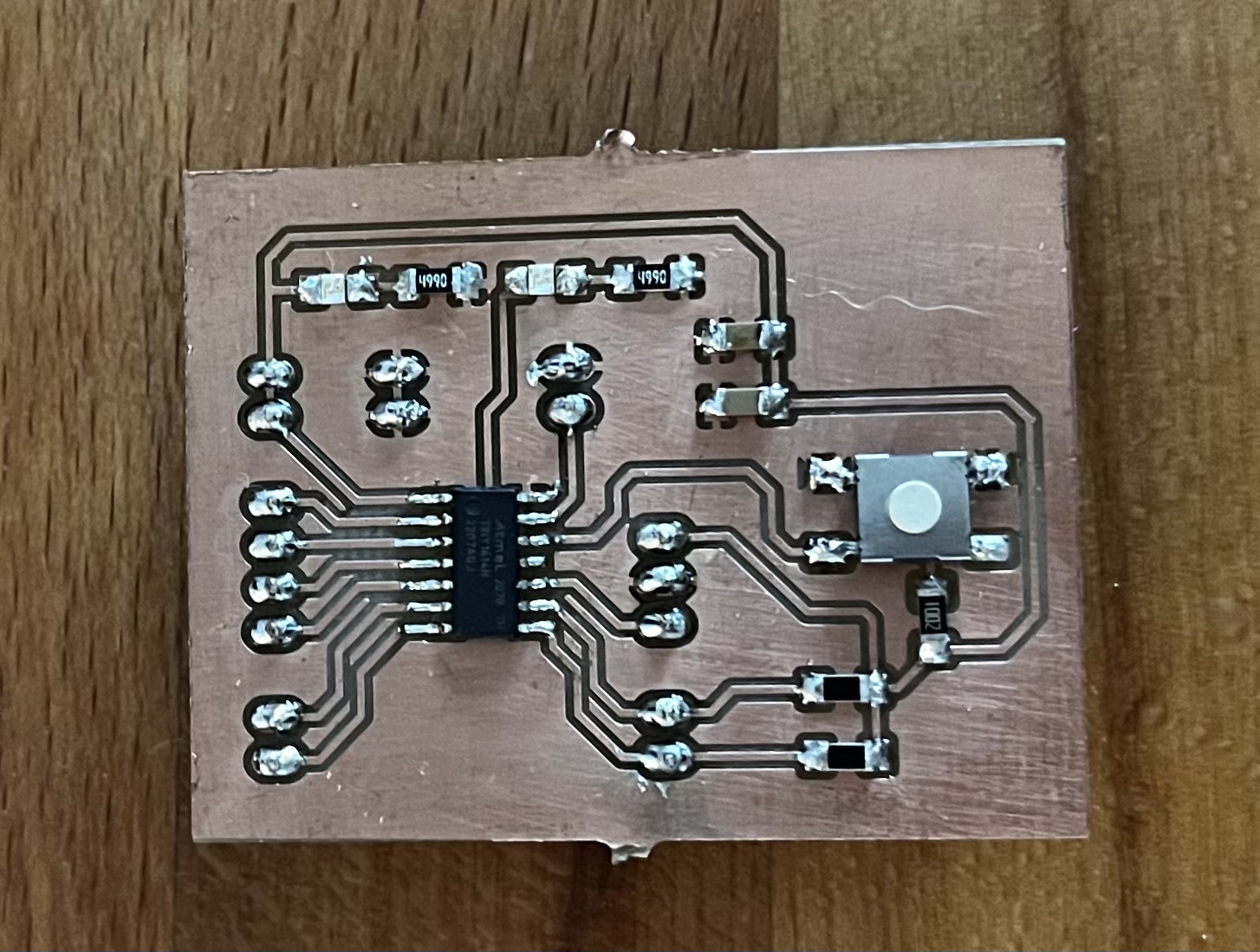
Finally, all the components had to be soldered onto the board and tested to ensure proper functionality.